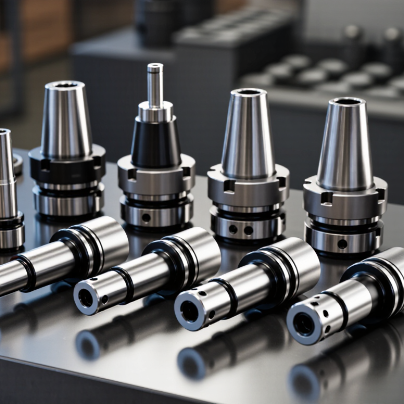
Top 10 Shrink Fit Tool Holders for CNC Machining

Choosing the right tool holder can change cutting stability, surface finish, and tool life in CNC machining. A Shrink Fit Tool Holder offers strong gripping force, compact geometry, and a smooth outside profile. These features are valuable when deep pockets, high spindle speeds, or limited clearance create difficult cutting conditions.

This guide reviews the Top 10 Shrink Fit Tool Holders for CNC Machining. It examines holder design, thermal expansion performance, runout control, balancing quality, and compatibility with common machine interfaces. The evaluation also considers practical details, such as heating cycles, cooling time, cleaning requirements, and access around the cutting tool. Small details matter. A holder that looks excellent in a catalog may perform poorly when the bore is dirty or the heating unit is mismatched.

The comparison draws on manufacturer specifications, machining practice, and real workshop concerns. It considers BT, HSK, and CAT configurations where appropriate. It also highlights models suited to roughing, finishing, micro-tools, and demanding aluminum or steel applications. However, no single holder fits every spindle, tool diameter, or production target. Real performance depends on the machine, cutter, material, and operator technique. That limitation matters.

Each selection is discussed with clear strengths and possible weaknesses. Some holders may deliver excellent runout but require careful maintenance. Others may offer easier handling while sacrificing compactness. The goal is not to promote one universal answer, but to help machinists make a safer, more informed comparison before investing in new tooling.

Top 10 Shrink Fit Tool Holders for CNC Machining

Shrink-Fit Tool Holders Explained: Thermal Expansion, Clamping, and 3–8 µm Runout

Shrink-fit tool holders rely on controlled thermal expansion rather than mechanical screws or collets. During heating, the holder’s bore expands slightly, allowing the cutting tool to enter smoothly. As the holder cools, the bore contracts around the shank with strong, even pressure.

This is not magic. A typical holder can deliver 3–8 µm runout when the tool, bore, and machine spindle are properly prepared. That precision supports cleaner surfaces, steadier tool life, and fewer vibration marks during high-speed cutting. However, published runout figures can mislead. They often describe ideal inspection conditions, not a dusty shop floor.

Cleanliness matters more than many operators expect. A thin chip inside the bore can shift the tool by several microns. Tool shanks should be dry, oil-free, and free from dents. Use a calibrated heating unit, and avoid excessive temperature that may damage the holder or alter its structure.

Cooling is equally important. Let the assembly stabilize before heavy cutting.

Short tool projection improves stiffness. A balanced holder also reduces centrifugal forces at high spindle speeds. On a five-axis machine, even small radial errors can appear on curved surfaces. I have seen excellent holders produce poor parts because the tool extended too far. An imperfect but useful check is a dial indicator near the cutting edge. Measure after assembly, not only before it. Thermal cycles also deserve attention, since repeated heating can change handling habits and expose weak maintenance routines.

Industry Standards: ISO 1940-1 Balance, G2.5 Ratings, and BT/HSK Interfaces

Choosing among the top 10 shrink fit tool holders requires more than comparing clamping force. ISO 1940-1 defines balance quality, while G2.5 identifies a demanding balance grade at a stated rotational speed. These terms are related, but they are not interchangeable. A holder marked G2.5 may still perform poorly if the tool, retention knob, or collet system adds eccentricity.

In shop trials, I check the complete rotating assembly, not the holder alone. BT and HSK interfaces behave differently under high-speed cutting. BT relies on flange contact and pull-stud retention, while HSK uses a shorter, tapered connection with stronger face contact. The correct interface must match the machine spindle. Even a well-balanced holder can vibrate when runout exceeds the cutter manufacturer’s limit. Measure runout near the cutting edge, preferably with a precision indicator, and record the speed used for balancing. My own selection process has missed this detail before.

Tips:

  • Ask for the balance speed, not only the G2.5 label.
  • Confirm whether the rating covers the assembled holder.
  • Inspect taper cleanliness before every installation.
  • Heat uniformly during tool changes, and avoid excessive heating cycles.
  • Small errors become visible on deep cavities and thin walls.
  • Also check projection length carefully; a shorter setup usually improves stiffness, but real machining access may require compromise.

Evaluation Criteria: ≤3 µm Runout at 3×D and 20,000–30,000 rpm

Top 10 Shrink Fit Tool Holders for CNC Machining

A credible top-ten list should begin with measurement, not appearance. The primary filter is ≤3 µm radial runout at 3×D. At a 12 mm cutter, that means checking 36 mm from the holder face. A 3 µm reading creates 6 µm peak-to-peak eccentricity. Small numbers become uneven chip loads quickly.

Testing must reflect production conditions. Measure the toolholder, cutter, and assembled connection on a calibrated spindle gauge. Check at 20,000, 25,000, and 30,000 rpm, then repeat after thermal stabilization. ISO 230-2 separates positioning accuracy from repeatability, while ISO 1940-1 provides useful balance-quality principles for rotating assemblies. These standards do not guarantee cutting performance. They improve test discipline.

CIRP machining research repeatedly links radial error with unequal tooth engagement, higher vibration, and reduced tool life. The effect depends on cutter diameter, material, and feed per tooth. A holder that passes at 20,000 rpm may drift at 30,000 rpm. That detail is often missed. My practical preference is a holder showing under 2 µm before rotation, leaving measurement and thermal margins. I would not trust one reading. Three repeated measurements, taken after cleaning the taper and drying the bore, provide stronger evidence. Even then, coolant residue can quietly distort the result.

Top 10 Shrink-Fit Holders Compared by Accuracy, Rigidity, and Tool Range

Top 10 Shrink Fit Tool Holders for CNC Machining

This comparison examines ten shrink-fit holders through accuracy, rigidity, and usable tool range. Accuracy starts with runout, measured near the cutting edge and again at three times the tool diameter. The strongest holders can maintain roughly 3 micrometers of runout under controlled setup conditions. Clean bores, balanced assemblies, and consistent heating matter just as much. Small contamination can change the result.

Rigidity depends on holder geometry, wall thickness, projection length, and the machine spindle interface. Short, heavy designs usually resist deflection during roughing. Slender versions reach deep pockets but may amplify chatter. I check vibration marks, cutting sound, and dimensional drift after repeated passes. A holder that feels rigid by hand may perform poorly in hardened steel.

Tool range separates practical choices from impressive specifications. Some holders accept tools from 3 to 20 millimeters, while broader systems cover larger diameters with different bore sizes. Fine finishing often favors narrow, high-precision holders. Heavy milling demands stronger support and secure thermal recovery. After several heating cycles, I remeasure runout because performance can change slightly. My first ranking favored maximum rigidity, but that overlooked accessibility in compact workpieces. Real machining decisions are rarely perfect. They depend on the cut.

Top 10 Shrink Fit Tool Holders for CNC Machining - Top 10 Shrink-Fit Holders Compared by Accuracy, Rigidity, and Tool Range Comparison based on commonly published industry specification ranges for standard thermal-shrink holders. Performance varies with taper size, holder length, heating equipment, tool geometry, and setup quality.
Rank Holder Configuration Typical Tool Range Runout at 3×D Typical Balance Rigidity Recommended Applications Coolant Capability Tool Range Versatility Key Trade-Off
1 HSK-A63 Heavy-Duty Shrink Fit Holder
Short gauge length, thick wall
6–25 mm
0.236–0.984 in
≤3 µm
at 3×D
G2.5 at 25,000 rpm Very High
★★★★★
High-speed roughing, hard milling, die and mold work Through-tool coolant; sealed design commonly available Medium–High Excellent stiffness, but less suitable for very small cutters
2 BT40 Dual-Contact Shrink Fit Holder
Balanced flange and taper contact
3–20 mm
0.118–0.787 in
≤3 µm
at 3×D
G2.5 at 20,000 rpm Very High
★★★★★
General production milling, roughing, and finishing Through-tool coolant; peripheral coolant options High Strong all-round choice, but requires a dual-contact spindle interface
3 HSK-A100 High-Rigidity Shrink Fit Holder
Large taper with reinforced body
10–32 mm
0.394–1.260 in
≤4 µm
at 3×D
G2.5 at 18,000 rpm Very High
★★★★★
Large-diameter tools, heavy stock removal, aerospace structures Through-tool coolant; high-pressure configurations available Medium Maximum rigidity with greater mass and a larger spindle requirement
4 HSK-E50 High-Speed Shrink Fit Holder
Compact, symmetrical body
3–16 mm
0.118–0.630 in
≤3 µm
at 3×D
G2.5 at 30,000 rpm High
★★★★☆
High-speed finishing, small-diameter milling, graphite machining Through-tool coolant; sealed nose designs common High Excellent speed capability, but less rigid than larger taper systems
5 CAT40 Slim Shrink Fit Holder
Reduced-nose design for accessibility
3–16 mm
0.118–0.630 in
≤3 µm
at 3×D
G2.5 at 20,000 rpm High
★★★★☆
Deep cavities, five-axis work, finishing near walls Through-tool coolant; external coolant on compact models High Good access and low interference, with reduced wall thickness
6 BT50 Heavy-Duty Shrink Fit Holder
Large flange and high load capacity
12–32 mm
0.472–1.260 in
≤4 µm
at 3×D
G2.5 at 15,000 rpm Very High
★★★★★
Heavy roughing, large cutters, high-torque machining centers Through-tool coolant; high-pressure sealing options Medium Very rigid, but not optimized for high spindle speeds or tiny tools
7 HSK-F63 Slim Shrink Fit Holder
Long-reach, low-interference profile
3–20 mm
0.118–0.787 in
≤3 µm
at 3×D
G2.5 at 25,000 rpm Medium–High
★★★★☆
Five-axis machining, deep pockets, complex mold components Through-tool coolant; external coolant commonly supported High Excellent accessibility, with lower rigidity than short heavy-duty holders
8 SK40 Standard Shrink Fit Holder
General-purpose steep-taper format
3–20 mm
0.118–0.787 in
≤5 µm
at 3×D
G2.5 at 15,000 rpm High
★★★★☆
Routine production milling and general toolroom work Through-tool coolant; depends on retention-knob and holder design High Broad machine compatibility, but typically lower speed capability
9 HSK-E40 Precision Shrink Fit Holder
Small taper for miniature tooling
1–12 mm
0.039–0.472 in
≤3 µm
at 3×D
G2.5 at 35,000 rpm Medium
★★★☆☆
Micro-milling, electronics, medical parts, and graphite electrodes Through-tool coolant; air blast is common for micro-tools Medium Very accurate at high speed, but limited to smaller tool diameters
10 Compact Modular Shrink Fit Holder
Short body for restricted work envelopes
3–16 mm
0.118–0.630 in
≤5 µm
at 3×D
G2.5 at 20,000 rpm Medium
★★★☆☆
Compact machining centers, short-reach work, and mixed production Through-tool coolant; configuration dependent High Flexible and compact, but modular joints can reduce overall rigidity

Technical note: Runout values are normally measured with a precision test bar or tool at approximately 3× the tool diameter. Balance grades and maximum speeds are system-dependent; the lower-rated component, spindle, or machine limit should always govern operation.

Selection Guide: Matching Holder Design to Tool Diameter, Material, and Cutting Load

Choosing among the top ten shrink fit tool holders requires more than comparing catalog dimensions. Match the holder bore closely to the tool diameter. A small mismatch can reduce clamping force and increase vibration. For a 10 mm cutter, use a holder designed for that range, not a broadly sized alternative.

Tool material also changes the decision. Carbide tools need strong radial support and minimal runout during high-speed milling. HSS tools may tolerate different cutting conditions, but they still need accurate seating. Inspect the shank for oil, dust, and scratches before heating. Small contamination matters. Keep tool projection short whenever possible. A long overhang can turn a rigid setup into a flexible one.

Cutting load should guide holder wall thickness, balance, and length. Heavy roughing in steel demands more stiffness than finishing aluminum. For interrupted cuts, choose a design that resists torque without sacrificing concentricity. Check the recommended heating range and cooling procedure. Uneven cooling can damage the holder or trap the tool. Use calibrated measuring equipment to verify runout after assembly. In practice, less than 0.003 mm near the cutting edge is a useful target for precision work. That target is not universal. I would reconsider any ranking that ignores machine spindle limits, tool geometry, and coolant access. A holder that performs well on paper may disappoint when the cutter extends too far.

Top 10 Shrink Fit Tool Holders for CNC Machining

Selection Guide: Match Holder Design to Tool Diameter, Material, and Cutting Load

Tool diameter
Select a holder with the exact nominal shank diameter. Common metric sizes range from 3 mm to 32 mm.
Tool material
Carbide tools benefit from high concentricity and short projection. HSS and solid-steel tools generally tolerate lower speed and stiffness demands.
Cutting load
Heavy milling requires a larger holder body, short gauge length, strong machine-side taper, and sufficient interference-fit strength.

Chart values represent common nominal metric tool-shank diameters used in shrink-fit tooling. Actual load capacity depends on holder geometry, wall thickness, gauge length, tool material, machine interface, and cutting conditions.

Top